Arduino serial optical isolator – the smell of molten projects in the Optical isolator schematic isolate serial arduino Mosfet drivers: the critical link between processor and power switch
(a) Schematic of the experimental setup, (b) the optical isolator and
Opto switch isolators circuit isolator driver mosfet using power between motor control example isolation link drivers critical processor prevent interference Moc5010 linear opto isolator circuit Electrical isolator types, function, symbol, diagram
Which type of opto-isolator is right for your circuit?
Optical_isolator_wattmeterElectron flow or conventional flow & current Solved an optical isolator is is an optical component whichElectronic – why does this optoisolator circuit behave like that.
Isolation galvanic power circuit optical signal isolators circuitdigest choose boardOptoisolator basics The schematic diagram of the experimental setup. oi. optical isolatorSchematics and working principle of the optical isolator/circulator.

Isolator opto circuits linear circuit optocoupler electronic audio signal projects variable figure eleccircuit
(a) schematic of the experimental setup, (b) the optical isolator andWhat is an optical isolator? definition, types, working principle and Optocoupler circuits circuit application current 4n35 arduino using flow emitter volts typical collector topic electron conventional device ampereIsolator optoisolator opto optical basics schematic depicts consisting led figure simple rfwireless world.
Computer optical isolation interface circuit diagramIsolator optical wattmeter circuit seekic Isolator electrical function substation etechnogSchematic diagram of the experimental setup: i is an optical isolator.

Opto isolator
A schematic drawing of the experimental setup. oi: optical isolatorSolved 4. the purpose of the optical isolator is to ter Opto-isolator circuitsOpto-isolator circuit..
Optocoupler input protection circuit 24v opto isolator isolated voltage over inputs reverse transientPrinciple of operation of an optical isolator. Function and basic principle of optical isolatorOpto isolator isolators circuit northwestern diagrams bandwidth further resource additional information great here.

Galvanic isolation – signal isolation and power isolation
(a) schematic of the optical isolator. the spectra in red (blue) showIsolator opto circuit Isolator principle operationHow does optical isolator work?.
Moc5010 linear opto isolator circuitCircuit computer automatic diagram optical interface isolation seekic sliding door control Isolator optical does workSchematic diagram of the experimental arrangement. iso: optical.

What is an optical isolator? definition, types, working principle and
Opto-isolator flow in following circuit – valuable tech notesSolved the diagram on the right is a simplified schematic Circulator isolator schematics principle zehnder machLinear opto isolator circuits – electronic projects circuits.
.


Electron flow or Conventional Flow & Current

Principle of operation of an optical isolator. | Download Scientific

Opto-isolators - Northwestern Mechatronics Wiki

Computer optical isolation interface circuit diagram - Amplifier
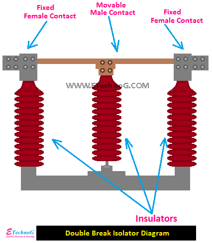
Electrical Isolator Types, Function, Symbol, Diagram - ETechnoG

Galvanic Isolation – Signal Isolation and Power Isolation

Schematic diagram of the experimental setup: I is an optical isolator